TechWorksHistory
So here we have a bit of a post that captures some of the history and background on how the TechWorks ECS Mitsubishi Controller came to be. I'm Duke3k & I live in the foothills of Denver
these are the cars that I originally developed the controller for :

They are mint Mitsubishi 3000gt VR4's. The one on the right is a '98 VR4 & the One on the left is a super rare '95 Spyder Convertible Version.
So here's how this project got started:
The early model Mitsubishi 3000gt VR's (including that '95) have a factory included Electronically Controlled Suspension(ECS) system. It was pretty much over the top and kinda ahead of it's time. It has as sensor inputs to the ECS controller - a single axis G-sensor ,a Throttle input feed, Steering Wheel sensor inputs, Brake Pedal input, and a user selection switch on the console. With all those inputs the factory ECS controller controls the 4 adjustable shocks(struts) in the car. Each strut is capable of being commanded by the ECS controller into a Hard , Medium or Soft setting that primarily adjusts the Shock Rebound dampening rates on the fly. There's a motor (not a stepper) that is physically inside the strut that when power is applied rotates a shaft and changes the orifice opening size thru which strut hydraulic fluid squirts thru. the bigger the opening more fluid flows thru on rebound = softer rebound = smoother rider. Smaller opening = less fluid thru orifice on rebound = stiff sporty suspension.
Mitsubishi completely eliminated the system starting in late '95. So the '98 above did not have it when I bought it. ![]()
This bugged me to no end - so I decided that I wanted to retrofit in this controllable suspension system into my '98 VR4. The '98 VR4 (and 95, 96,97 & 99) has none of the sensors , none of the factory wiring harness feeds necessary and the struts that were in it were the later model fixed rate struts - not the controllable ones.
What I decided to do was to remove the non-controllable factory struts & replace them with the factory controllable ones and then build a manual controller to control the struts (skipping the sensors ) .
Back in 2010 I had not messed with Micro-controllers much so this was my first design (that I never ended up using )based on TTL circuits - it's only enough circuit to control one strut:
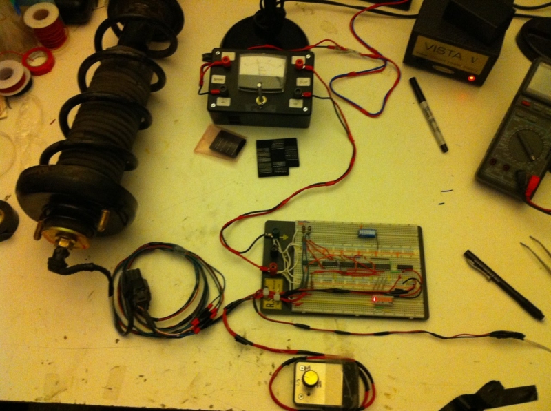
Here's the actual design prototyped on a breadboard and I got it workding. You can see the bread board connecting to the test factory ECS strut cartridge that I use. It's connected via a spliced cap connector plug that plugs into the top of the factory strut. It has five connections - Motor, Signal Switches S1 & S2 and two ground wires. :
Here is a youtube video showing the use of the ttl circuits in action:
While the TTL circuits worked they would have been difficult to easily add behavior or make changes to the way the system operated. A much better alternative was a micro controller based solution So I dove into the arduino platform and went with the Standard Arduino for the time period - the Duellimanov Amtel328 16mhz 32kb.
Here is a youtube video showing the use of an Arduino & a prototyping board controlling a single strut:
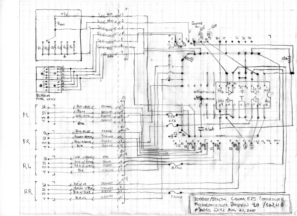
What I finally came up for the design was this hand drawn prototype design that could be used to build an Arduino Shield.
- The shield was used to build out the strut driver circuits using a TI quad H-Bridge Motor Driver chip
- The Control Selector Switch was a 5 position Rotary Selector Switch that I use to create a Voltage divider that fed into one of the analog ports on the Arduino.
- Four BlinkM I2C addressable RGB leds were used as strut & diagnostic status indicators .
- Each strut had 5 wires going to it (9v Motor Power Wire, 2 Grounds and 2 internal status switches)
- Each Strut used 3 ports each (12 total) to the arduino : 1- Motor Enable, & 2- Digital inputs for the status (open or closed ) of the S1 & S2 strut mode sensor switches.
That lead to this Arduino full on implementation that had a custom prototyped shield piggybacked onto it:
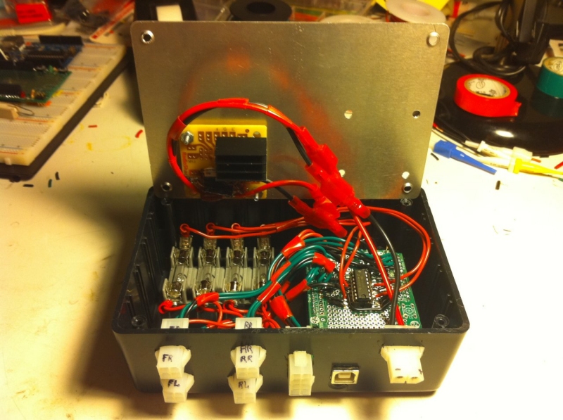
Here's it is all buttoned up ready for installation:
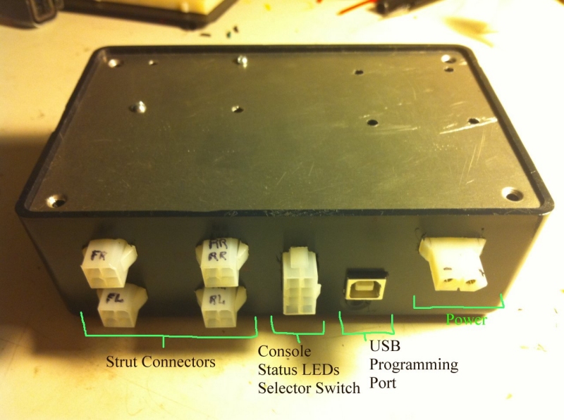
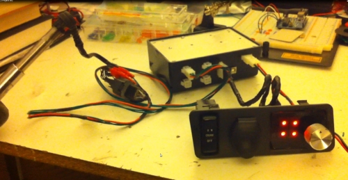
Here's all the final pieces of the custom Arduino Based Build assembled & being tested including the console controls/display. -Thats a 4 position rotary switch for the mode selection. & those are 4 addressable I2C BlinkM LEDs that display the strut status/diagnostic info.
Here's a youtube video of the picture above:
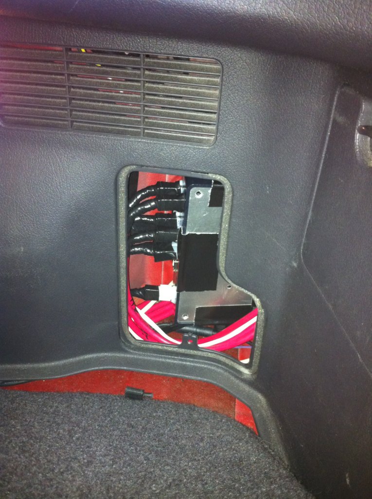
Here it is installed in the back of my 3000gt, I used cat5 for the five runs of wire needed to make the wiring harness to retrofit into the car. ( 4 runs to each of the struts and 1 run to the console control display & lastly a switched +12v power and ground feeds. Oh and you gotta love Gorilla tape. ... I was stil debuging & i didnt want to keep messing with the screws.
And that's the way it was for two years...I ran with that custom build in my car... I fairly regularly attended the local car meets for the 3000gt's in the area and kept getting asked - hey when are you going to make these so that we can do that too? Well around 2012 - I got motivated and came up with this custom - all one board solution - that still based on the Arduino software IDE platform and hardware - but all on a single board that takes up less space and is easier to build:
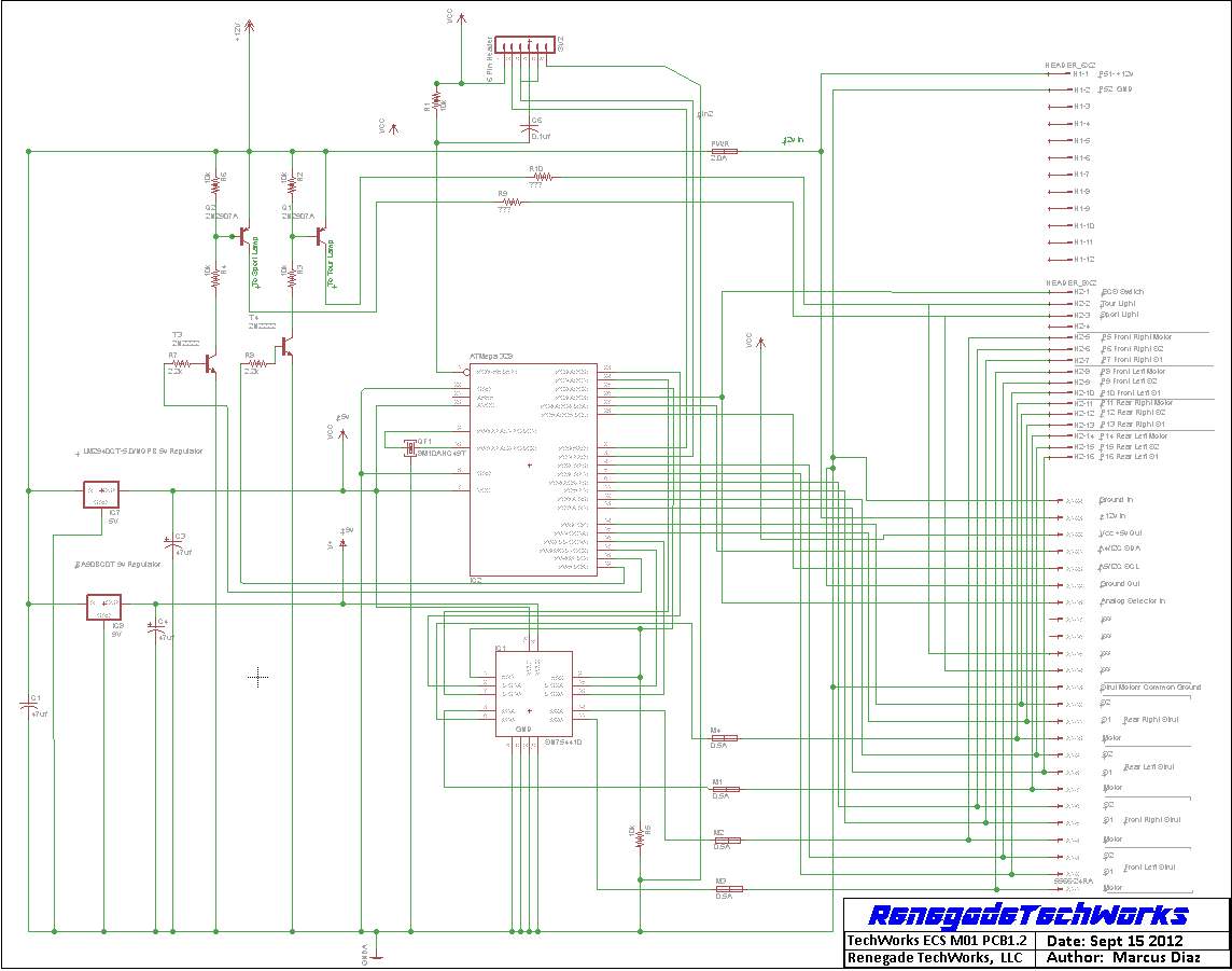
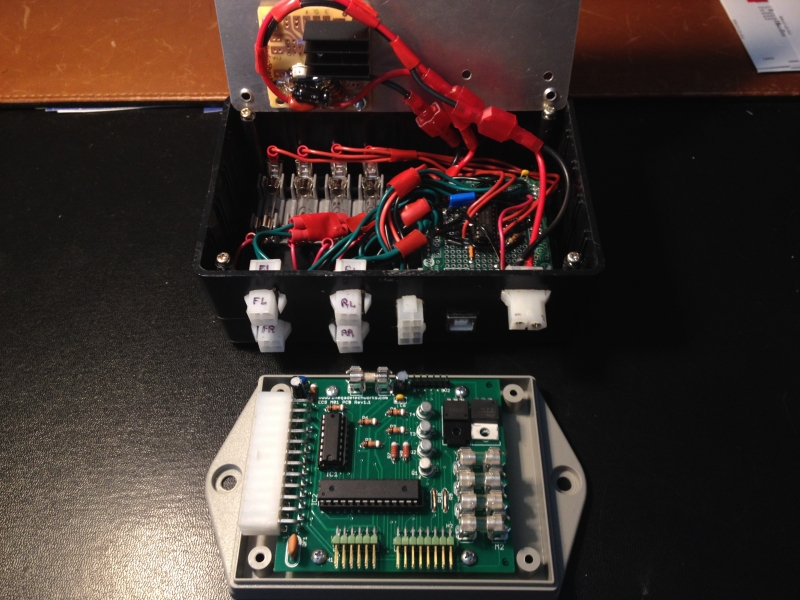
Here's the production version of single board design - its basically an AMtel328 arduino simplied design with the additional circuitry that used to be on the shield piggy back :
And here's an overview youttube Vid of the production build being demonstrated. In the final production version I switched from the 4 I2c controlled BlinkM leds to a simpler set of 4 - WS2801 chained 12mm Pixel Leds. You"ll see the WS2801's in the video.
Here's a final overview video of the system being demonstrated:
Here is a final video showing the system installed in my mistubishi 3000gt VR4
I started selling these in Sept/Oct of 2012 and have shipped them as far as England & Australia. One major design addition that has made them popular is that they are plug compatible with original OEM ECS controllers - so if your an early model 3000gt owner and your factory controller dies you can replace it with a TechWorks controller (for $100 cheaper). Manual control only - but a lot of people like it that way it turns out.
Well thats it. Hope you enjoyed the story. If your interested - all the Arduino open source code and electrical schematics are available for download on http://www.renegadetechworks.com
Cheers,
Duke3k
p.s. Nate anytime you want to claim that "beerware open source license" - just let me know and I'll drive up and pay my dues . ![]()